Buying moulded plastic parts is not simply a matter of choosing a machine and approving a sample. The injection moulding process connects material selection, tooling design, machine settings, quality checks, and delivery planning. Each stage can affect part strength, appearance, cost, and production stability. A small gate mark may reveal a filling problem. A slight colour change may indicate moisture, heat, or inconsistent material handling. Buyers who understand these details can ask sharper questions and identify risks before mass production begins.
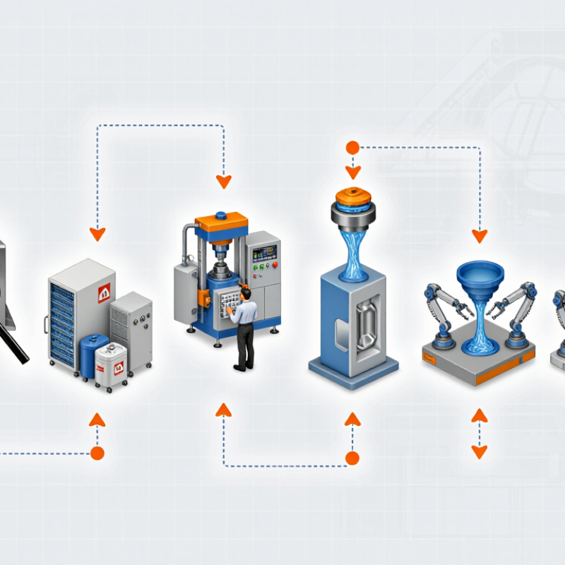
This guide follows the ten key injection moulding process steps buyers should know. It explains how a drawing becomes a finished component, from resin preparation and mould inspection to trial runs, inspection, packing, and shipment. Practical checkpoints are included, such as checking cavity balance, measuring critical dimensions, reviewing cycle time, and requesting inspection records. No factory gets every trial perfect. That is normal, but unexplained deviations deserve attention. A supplier’s confidence should be supported by data, not only attractive samples. Ask what changed, why it changed, and how the correction was verified. Small details matter. Buyers should also remember that a low unit price can hide tooling adjustments, high scrap rates, or unstable processing conditions. With a clear view of each step, procurement teams can compare suppliers more fairly, communicate requirements precisely, and build a more dependable sourcing decision.
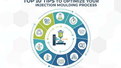
Top 10 Injection Moulding Process Steps Buyers Should Know
Material selection shapes every later moulding decision. Buyers should define strength, flexibility, heat resistance, surface finish, and expected service life before requesting quotations. A low-cost resin may look attractive, but poor impact resistance can create expensive field failures. Check the resin’s moisture sensitivity, drying temperature, shrinkage rate, and recycled-content limits. Keep the data sheet available.
Mold design must match the material and the part’s function. Engineers review wall thickness, draft angles, ribs, bosses, parting lines, and ejection points during preparation. Uneven walls can produce sink marks or warpage. Sharp internal corners can increase stress and complicate machining. Small details matter. Gate location also affects weld lines, filling balance, and visible surfaces. Cooling channels should follow the heat pattern, not simply repeat an old layout.
Experienced buyers ask for mold-flow analysis when the geometry is complex. They also request tolerance studies and trial-shot reports before approving production. A drawing alone cannot reveal every risk. I have seen projects with excellent CAD models fail because the chosen resin was too moisture-sensitive for the available process. That mistake was avoidable. Design reviews should include the molder, toolmaker, and quality team. Still, no simulation replaces measured parts from a properly controlled trial.
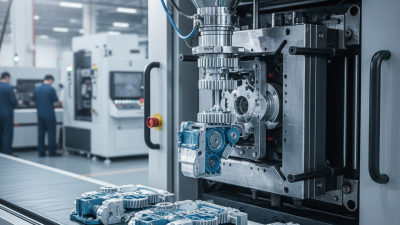
Before production starts, technicians inspect the mold, machine, and material records together. The mold must match the machine’s platen size, tie-bar spacing, ejector position, and injection capacity. Small mismatches create delays. Experienced teams clean the parting line and check vents, cooling channels, guide pins, and cavity surfaces. They also confirm that clamps, hoses, and lifting points are secure before applying pressure. A dry run helps reveal unusual resistance or misalignment without risking material waste.
Machine parameters should follow the material supplier’s technical data and the mold’s proven process window. Operators set barrel temperatures by zones, then verify actual readings rather than trusting the display blindly. Injection speed, screw position, holding pressure, cooling time, and back pressure need controlled adjustments. One change at a time. This makes defects easier to trace. For example, short shots may indicate insufficient filling pressure, cold material, restricted vents, or an incorrect transfer position. Warping can reflect uneven cooling, excessive packing, or a mold temperature that was never stabilized.
I have seen teams chase pressure settings while ignoring a blocked water line. That mistake is common, and expensive. Record the initial settings, melt temperature, cycle time, and first-article measurements. If the result looks acceptable, repeat the cycle; one good part proves very little. Buyers should request these records, because consistency matters more than a single polished sample.
| Step | Process Step | What Buyers Should Verify | Typical Parameter or Requirement | Quality and Safety Check | Buyer-Relevant Result |
|---|---|---|---|---|---|
| 1 | Review the Mold and Part Data | Confirm resin type, part weight, projected area, wall thickness, shrinkage allowance, gate position, ejection method, and cooling-channel layout before installation. | Material: Confirm the exact resin grade and drying requirement. Part review: Check critical dimensions and cosmetic surfaces. |
Verify that the mold design, machine capacity, and material specification are compatible. Confirm the latest approved drawing and revision level. | Reduces the risk of incorrect setup, dimensional variation, and avoidable mold changes. |
| 2 | Select a Suitable Machine | Match the mold to the machine based on clamping force, tie-bar spacing, platen dimensions, shot capacity, injection pressure, and maximum mold height. | Clamping force: Commonly estimated from projected area and material-specific clamp-pressure requirements. Shot size: Use a practical shot range rather than operating at the extreme limit. |
Ensure the mold fits within the tie bars and platens. Confirm that the machine can safely open, close, inject, and eject the mold. | Provides sufficient filling capability while avoiding excessive machine size and unnecessary energy use. |
| 3 | Install and Align the Mold | Clean the platens, position the mold, align the locating ring and nozzle center, and secure the mold with suitable clamps or approved mounting hardware. | Alignment: Nozzle, sprue bushing, and machine centerline should be concentric. Clamping: Tighten mounting hardware evenly according to the approved setup procedure. |
Inspect for damaged clamp slots, loose fasteners, exposed pinch points, and interference between the mold, platens, and machine components. | Prevents mold damage, leakage at the sprue, uneven loading, and unsafe operation. |
| 4 | Connect Water, Electrical, and Auxiliary Lines | Connect cooling circuits, hot-runner wiring where applicable, mold-temperature controllers, hydraulic or pneumatic cores, and ejection interfaces. | Cooling: Use separate supply and return lines for each circuit when practical. Temperature: Set the mold-temperature controller to the resin supplier's recommended range. |
Label circuits, check flow direction, test for leaks, and confirm that electrical connectors and hoses are correctly rated and secured. | Improves cooling balance, cycle consistency, operator safety, and mold serviceability. |
| 5 | Prepare and Dry the Resin | Verify material identity, lot traceability, moisture sensitivity, pellet condition, and any required colorant or additive ratio. | Drying: Follow the resin supplier's time and temperature specification; hygroscopic materials commonly require controlled drying before processing. Feed system: Keep the hopper and conveying system clean and dry. |
Use a moisture check when required. Avoid prolonged exposure of dried resin to ambient humidity and prevent material contamination. | Reduces splay, bubbles, brittleness, hydrolysis, discoloration, and inconsistent mechanical performance. |
| 6 | Set Barrel and Nozzle Temperatures | Configure heating zones from the rear of the barrel to the front, including the nozzle or hot-runner zones when applicable. | Temperature: Use the resin supplier's recommended processing window rather than a universal value. Example range: Many common thermoplastics process approximately between 180°C and 320°C, depending on resin type and grade. |
Allow the barrel to reach thermal stability. Check for blocked heaters, faulty thermocouples, nozzle drool, and signs of material degradation. | Supports stable melt viscosity, consistent filling, and reduced risk of burns or degraded material. |
| 7 | Configure Injection and Filling Parameters | Set injection speed profile, transfer position, maximum injection pressure, screw position, and decompression where required. | Injection speed: Begin with a controlled profile and optimize for short shots, weld lines, burn marks, and surface appearance. Transfer: Commonly controlled by screw position, pressure, or time. |
Use a short-shot study or staged filling trial to confirm the filling pattern. Keep the pressure limit high enough for filling but below the machine or mold safety limit. | Creates repeatable filling behavior and helps control flashes, hesitation marks, trapped air, and dimensional variation. |
| 8 | Set Packing, Holding, and Cooling | Establish holding pressure, holding time, cooling time, screw recovery speed, and back pressure based on part weight and dimensional requirements. | Holding pressure: Often set below peak filling pressure and optimized through part-weight and sink-mark studies. Cooling time: Increase until the part ejects without distortion or sticking. |
Compare part weight over successive shots. Check for sink marks, voids, warpage, flash, residual stress, and incomplete gate freeze. | Controls shrinkage, warpage, surface quality, cycle time, and final part dimensions. |
| 9 | Set Mold Opening and Ejection Functions | Configure mold-opening stroke, opening and closing speeds, low-pressure mold protection, ejector stroke, ejector speed, and core-sequence timing. | Mold protection: Use low pressure and low speed during the final closing movement. Ejection: Use the minimum effective force and stroke needed for clean release. |
Run the mold slowly in manual mode first. Confirm that slides, lifters, inserts, ejector pins, and part-removal equipment operate without collision. | Protects the mold, reduces part damage, and improves operator and automation safety. |
| 10 | Validate the Process and Record the Settings | Run consecutive cycles at stabilized conditions and record the approved machine settings, cycle time, part weight, inspection results, and material lot. | Stability: Confirm consistent cushion, peak pressure, screw recovery, mold temperature, and cycle time across multiple cycles. Documentation: Store the approved setup sheet with revision control. |
Inspect critical dimensions, appearance, flash, short shots, weld lines, sink marks, warpage, and functional features before production approval. | Provides a repeatable baseline for production, troubleshooting, quality audits, and future mold installation. |
Top 10 Injection Moulding Process Steps Buyers Should Know
Plastic melting, injection, and cavity filling determine whether a moulded part performs reliably. Plastic pellets enter the hopper, then move through a heated barrel. A rotating screw applies controlled heat and shear. The material should melt evenly, not burn or remain grainy. Barrel temperature, screw speed, and back pressure must match the resin. I have seen glossy parts fail because the melt was overheated internally.
During injection, the screw pushes molten plastic through the nozzle and runner system. Injection speed affects flow marks, weld lines, and trapped air. The cavity must fill steadily, with enough pressure to reach thin sections and distant corners. Proper venting is essential. Without it, compressed air may leave black marks or incomplete edges. Holding pressure then compensates for material shrinkage while the gate remains open. A perfect-looking sample can still reveal weakness after cooling, so dimensional checks and functional testing matter.
Tips: Ask for a filling analysis and trial report. Check melt temperature near the nozzle, not only the machine display. Inspect short shots to understand the filling pattern. Small vents can make a large difference. No setting works for every resin, and that is easy to underestimate. Review warpage, surface defects, and cycle stability before approving production.
The chart shows a representative 40-second thermoplastic injection moulding cycle. Plastic melting, injection, cavity filling, packing, and cooling are key factors that influence part quality, productivity, and equipment selection.
Reference profile for buyer planning: actual cycle times vary according to resin type, part thickness, mould temperature, machine capacity, and required surface quality. Plasticising and cooling may occur partly in parallel.
Cooling, Solidification, and Part Ejection
Cooling often controls the injection moulding cycle more than filling. A 2023 review in Polymers reported that cooling may consume roughly 50–70% of total cycle time. The exact share changes with wall thickness, resin type, and mould temperature. Thick ribs remain hot inside while their surfaces look solid. That hidden heat can create sink marks, warpage, or dimensional drift after ejection.
Use cooling channels close to thick sections, but keep their spacing consistent. Uneven cooling is a quiet source of stress. The U.S. Department of Energy’s Industrial Assessment Centers identify process cooling as a significant energy load in manufacturing plants. This makes flow rate and return-temperature monitoring practical, not decorative. A moulder should record coolant temperature, pressure, and cycle time together. One number alone can mislead.
Solidification should support safe ejection, not simply shorten the cycle. Ejecting too early may bend a thin wall around the pins. Ejecting too late wastes energy and reduces output. A 2022 technical review in Materials reported that polymer shrinkage and thermal gradients strongly influence residual stress and warpage. In production, a small draft angle and polished ejection surfaces can prevent visible drag marks. Still, perfect settings rarely survive every material batch. That is the uncomfortable part. Check parts after cooling, not only at the moulding machine. Examine corners, ribs, and gate areas under consistent lighting.
For buyers reviewing the top ten injection moulding process steps, finishing work often reveals process discipline. Trimming removes gates, flash, and sharp edges after ejection. Operators should use clean, suitable tools and consistent pressure. A rough gate can leave stress marks or affect assembly. Ask suppliers how trimming dimensions are controlled, not merely whether parts look acceptable. During one production review, a small flash line caught on a mating surface. The mould was stable; the trimming fixture was not. This detail changed the corrective action.
Quality inspection should combine visual checks with measurable evidence. Inspectors may verify critical dimensions using calibrated gauges, optical systems, or coordinate equipment. Sampling plans must reflect part risk, volume, and customer tolerances. Record short shots, sink marks, weld lines, color variation, and warpage. Keep inspection reports linked to the cavity, batch, machine, and settings. Ask for capability data when a dimension controls fit. A photograph helps, but it cannot replace measurement. Many reviews become too optimistic here.
Process optimization connects trimming and inspection to molding conditions. Engineers can adjust melt temperature, injection speed, holding pressure, cooling time, and tool temperature. Each change should have a recorded reason and measured result. Reducing cycle time sounds attractive. It can also increase warpage or hidden stress. Review trial parts after conditioning, not only while they are warm. Buyers should request a control plan, reaction limits, and sample approval criteria. No process is perfect. Good suppliers show what failed, what changed, and what still needs watching.